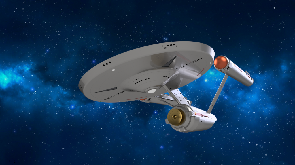
This project is my most ambitious yet. This is technically a revival of an old school project, modeling the entirety of the Starship Enterprise. Back then, armed with nothing more than basic extrude and fillet commands, I created something somewhat resembling the enterprise, but I was never pleased with the project. Now with some more experience under my belt, I decided to take another crack at a project that had always daunted me.

The first few steps were creating what would be, the primary hull (the saucer) the neck, and the secondary hull. The saucer was very straight forward to make, a simple sketch revolved around a created axis, (The green and red sketches, revolved around the yellow axis) The grooves on the hull were created by sweeping a 1cm circle along the green path, then using a circular pattern to pattern them around the hull.
The neck (the sketch in blue) was simply made by extruding the sketch in the XY plane.
The secondary hull along with its grooves was created by revolving the purple sketch to create the barrel shape I was looking for, the turquoise sketch was drawn on the XY plane and extruded to create the proper shape.
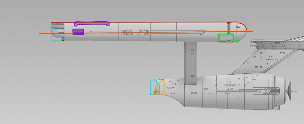
The first step in creating the warp nacelle (the red sketch) by first making a new work plane (the orange line) The nacelle was then revolved from the red sketch. With the basic shape in place, the details could then be put into place.
The registry number and pennant (NCC-1701 & Starfleet Insignia) were simply drawn on the nacelle work plane and extruded out. The details around the Bussard collector (the green sketches) were drawn, extruded, and then patterned using the circular pattern tool. The parts toward the back of the nacelle were drawn and mirrored to the other side of the nacelle, as they are symmetric.
The turquoise sketches were extrusions that removed material in order to create the proper shapes needed for the nacelles and for the shuttle bay. The orange sketch is a revolve to create the shuttle bay door and flange.
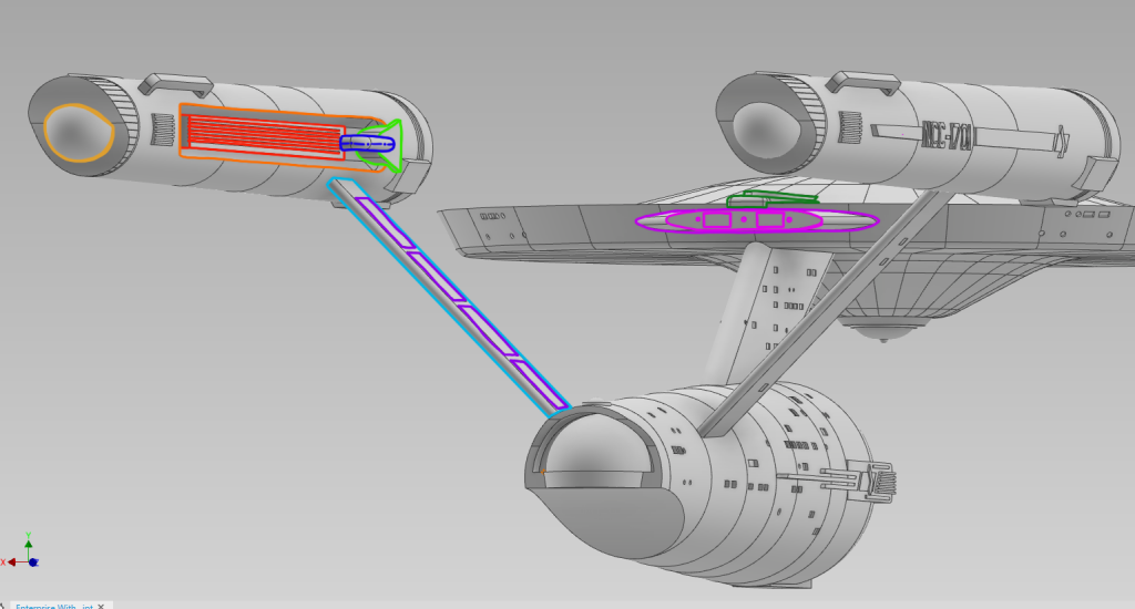
The inner warp nacelle details were next. An extrusion (orange sketch) was made to fit the warp field grills (red extrusion) and other parts of the nacelle. The blue piping was made by sweeping a circle sketch along a 3D Sketch (blue and blue dotted lines)
The Warp Nacelle Strut (Turquoise) was created by first creating another new work plane, then drawing a thin rectangle on it, connecting the nacelle to the secondary hull, and then simply extruding to the desired width. Fillets were then put in to round off the edges. Strut detailing (Purple) was just extrusions drawn on the surface of the strut.
The Impulse Engines had two major components. To create the shape needed, a bigger version of the pink sketch was drawn on an offset plane (Purple), with a basic loft joining them together. The actual impulse engines and detailing were drawn on the loft and extruded (Pink)
Finally, some miscellaneous detailing, the “balls” on the end of the warp nacelles (lighter orange) were simply a revolve of a circular sketch and the impulse manifolds (dark green) were just extruded sketches will fillets.
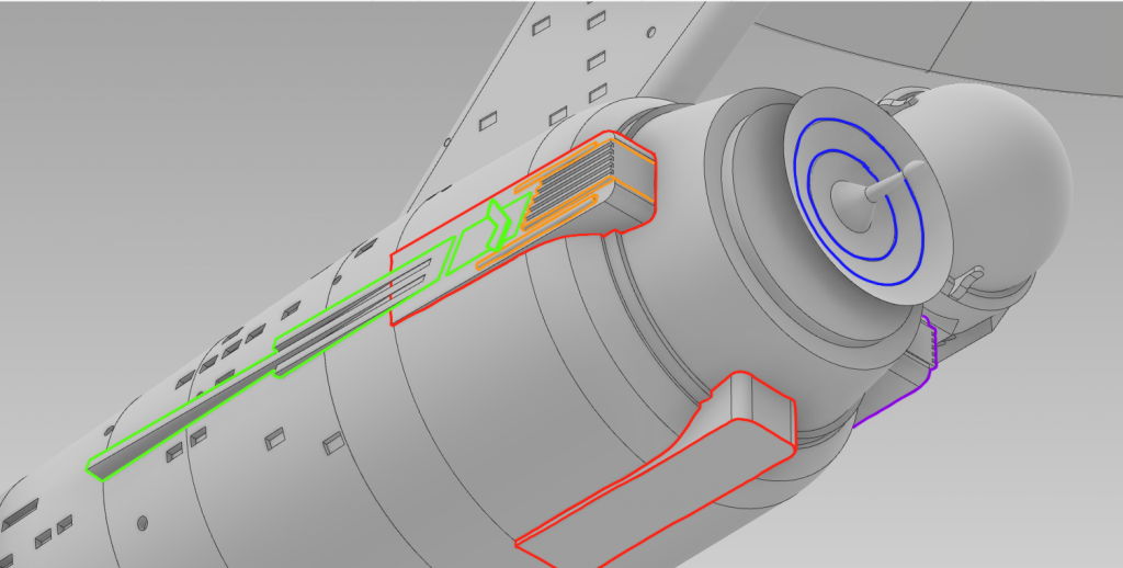
Secondary Hull detailing: Deflector dish struts were made and made in a circular pattern around the dish (Red) The bottom strut was left with no detail (as per reference drawing) The detailing (orange) were just made with extrusions, as were the Starfleet Pennant (Green) With the detailing in place, all these details were mirrored to the other side of the hull (purple)
Finally, a small correction was made with the deflector dish. Rings were added to the dish, better reflecting what was seen on the TV Show. This was done by simply editing the original secondary hull revolution sketch (Blue).
